Link Fault Pass Through
■ Background
Fiber media converters make it possible to connect two different media types such as twisted pair with fiber optic cabling. Introduced in the 1990s, media converters are important devices for interconnecting fiber optic cabling-based systems with existing copper-based systems. This allows networks to take advantage of the benefits of fiber (greater distance, protection from electromagnetic interference) in a cost-effective manner that leverages existing network infrastructures. Media converters can support several protocols, including Ethernet, Fast Ethernet, and Gigabit Ethernet. Media converters range physically from small standalone devices and PC cards, to large chassis systems Some media converters also support Power Over Ethernet (PoE).

In the above example, the PoE media converter delivers power to, and receives data from, the IP camera using a standard copper cable. The data is converted and sent through the fiber link to the switch.
■ Applications — Paired Media Converters
A common use of media converters is to connect multiple LANs in separate buildings or geographical locations. In this setup, two media converters are used, one on each end of the fiber link.
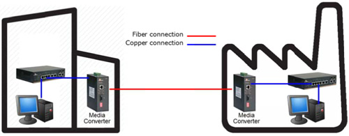
In the diagram above, paired media converters allow the copper-based LANs in the office and factory to communicate using the fiber link, even if the physical locations are distant (fiber-optic cable can transmit data over distances up to 100 kilometers).
■ Potential Drawbacks
However, in any fiber-copper topology with paired media converters, there is a disadvantage. If the copper link on one side of the fiber connection fails, the devices on the other side (such as switches) have no way of knowing that the link is down. They will continue to operate even though no data can be transmitted, and will not report an error to the system administrator.
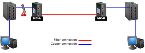
In the above example, the copper link on the left has failed. The switch and computer on the right will continue to operate as if the link were working, even though no data can be successfully transmitted.
■ Link Fault Pass Through
To overcome this shortcoming, Link Fault Pass Through (LFPT) provides constant monitoring of the links connected to the media converters. If either of the copper links fails, the media converter will pass the fail state on throughout the link, taking down the middle fiber link as well as the copper link on the opposite end. This prevents the connected switches from sending packets that would end up lost, and makes detection and troubleshooting much easier. If a redundant connection exists, the network can switch over to it immediately.
Using the above link failure example, LFPT would take effect as below:
1) The copper link on the left has failed. This could be due to something as simple as a cable becoming unplugged, or as problematic as a hardware failure in the switch.
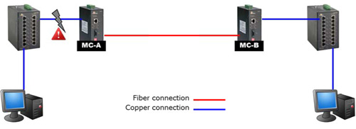
2) MC-A notifies MC-B of the link failure, and disables the fiber connection to MC-B.
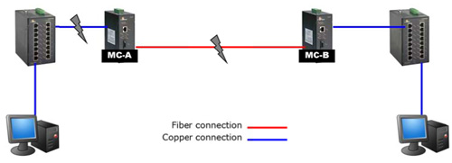
3) MC-B disables its copper link. The switch on the right will display the link down state on the corresponding LED indicator. If SNMP is enabled, the switch will send an SNMP alert to the network administrator.
■ Far End Fault
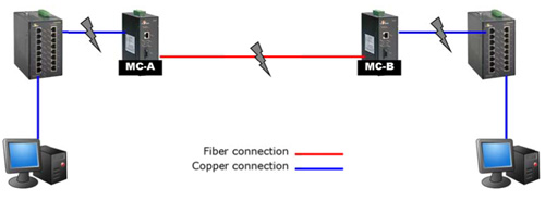
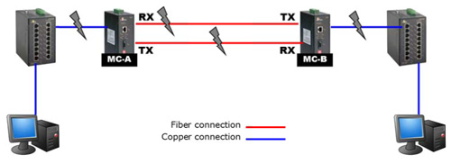
For faults that occur on the fiber link, Far-End Fault (FEF) is an IEEE 802.3u standard that allows both ends of a pair of fibers to be informed when there is a problem with one fiber. Without Far End Fault, it is impossible for a media converter’s fiber interface to detect a problem that affects only its TX (transmit) fiber. When a fault is detected, the media converter will transmit a Far-End Fault signal pattern over the fiber connection in order to inform the media converter at the far end of the fiber pair that the fault has occurred. Both copper links connected to the fiber link will be automatically taken down. This not only aids detection and troubleshooting, but also prevents data from being transmitted to a nonfunctioning link.
Far End Fault Operation:
1) MC-A detects a loss of signal in the RX (receive) cable of the fiber connection.
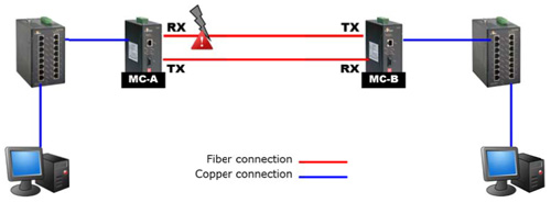
2) MC-A sends a Far End Fault signal to inform the MC-B that a fault has occurred. This disables MC-A’s TX (transmit) fiber.
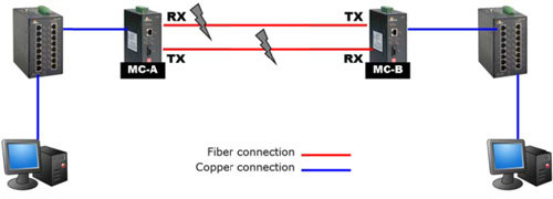
3) MC-A takes down its copper link. On the corresponding switch, the LED indicator shows link down state, and an SNMP trap is sent (if SNMP is enabled).
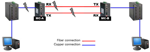
4) MC-B takes down its copper link. The connected switch LED indicator shows link down state, SNMP trap is sent (if SNMP is enabled).
■ Implementation Notes
LFTP must be used with media converters arranged in pairs, and both devices must support LFPT. If only one media converter is used, Far End Fault and LFPT functions will not work properly, because switches will not understand the LFPT message. Furthermore, it is recommended to use the same brand of media converter for each pair, because different vendors sometimes use proprietary LFPT and FEF protocols.
■ Summary
Media converters are flexible and cost-effective devices for implementing and optimizing fiber links in all types of networks. They play an important role in modern local and wide area networks, as these networks often employ multiple protocols and media types. Link Fault Pass Through and Far End Fault are essential tools that aid network administrators in diagnosing and troubleshooting network outages.


